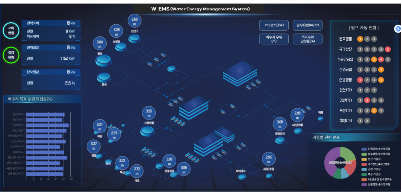
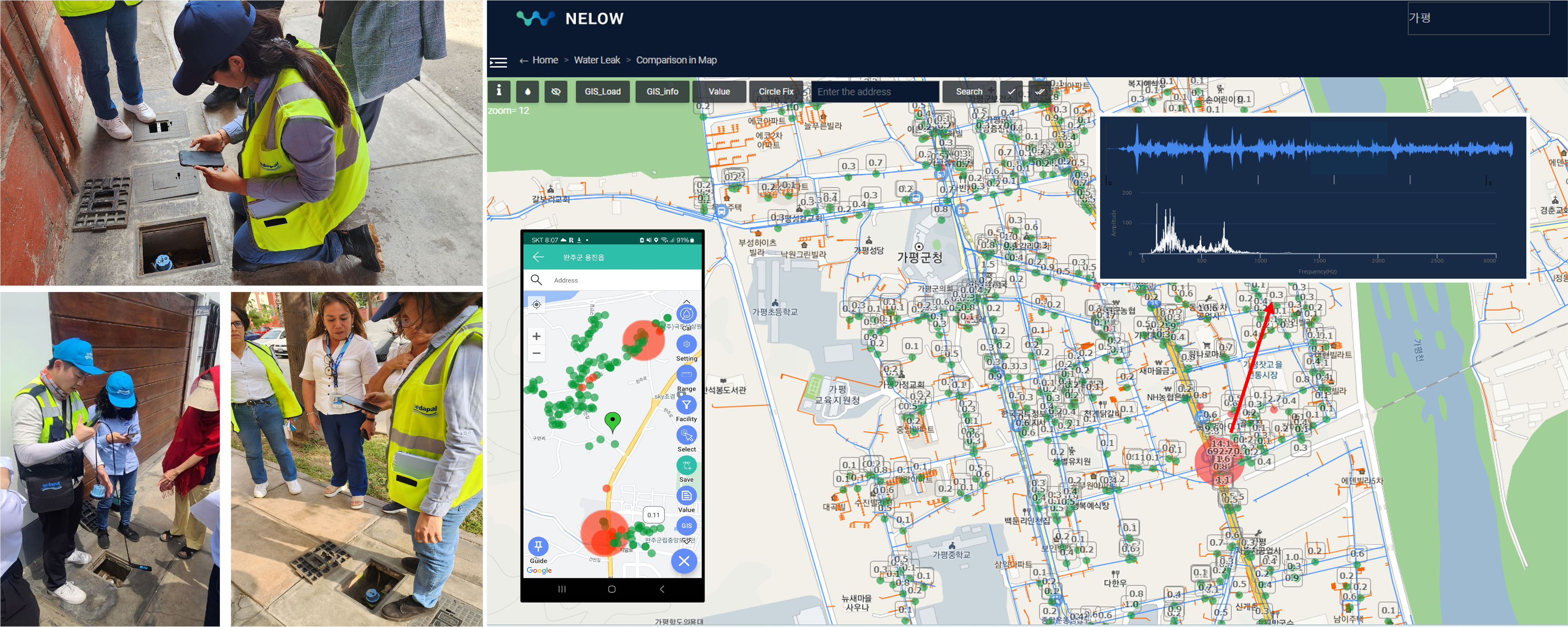
The Importance of AI in Water Management Systems
Water leaks in distribution networks can be a costly and persistent problem. However, with advancements in technology, managing and preventing water loss has become much more efficient.
Let’s explore how pressure monitoring and artificial intelligence (AI) are revolutionizing the way utilities tackle these challenges.
How Pressure Monitoring Enhances Leak Detection in Water Networks
Why Pressure Monitoring Matters
Pressure monitoring is a modern technique for detecting leaks in water systems. By placing sensors in key locations, water utilities can collect real-time data about the network’s performance. Unlike traditional manual inspections, pressure monitoring allows utilities to detect leaks quickly, minimizing water loss and preventing long-term damage.
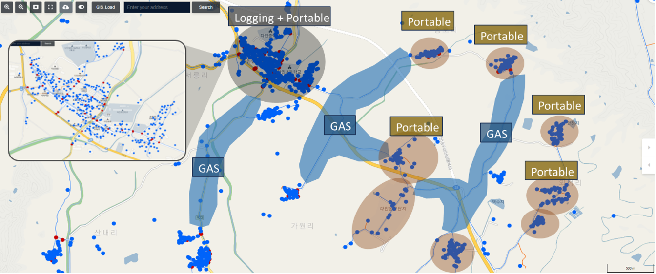
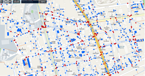
To get the most out of pressure monitoring, the network should be divided into smaller sections called District Metered Areas (DMAs). DMAs make it easier to monitor specific parts of the system. By strategically placing sensors on main pipes and smaller branches, utilities can capture a clear picture of the network’s health. This setup not only detects leaks but also pinpoints their locations for faster repair.

Figure 1: DMA organization in water supply network
Effective Sensor Deployment in AI-Driven Water Management Systems
Once the network is divided, pressure sensors should be deployed both on the main pipe and across these smaller DMAs or network branches. Placing sensors on the main pipeline allows for monitoring the overall system pressure, providing an overview of the general health of the network.
However, positioning sensors on smaller DMAs or branch lines offers the added benefit of more localized and detailed insights. These sensors can detect pressure fluctuations and potential leaks within specific sectors of the network, enabling quicker identification and isolation of issues in targeted areas. By using advanced water leak detection equipment for mainline and branch-level monitoring, utilities can achieve comprehensive coverage, improving leak detection accuracy and overall responsiveness of their leakage management systems.


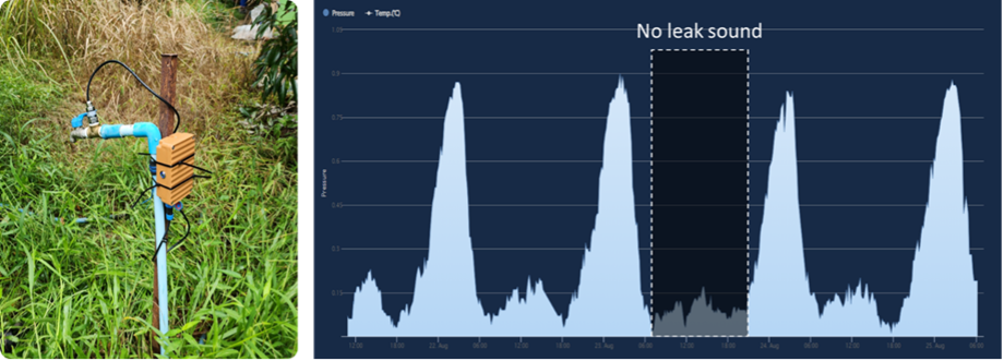
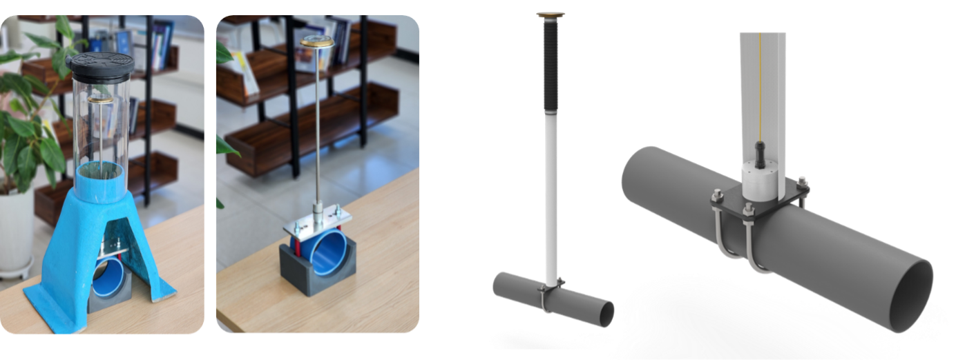
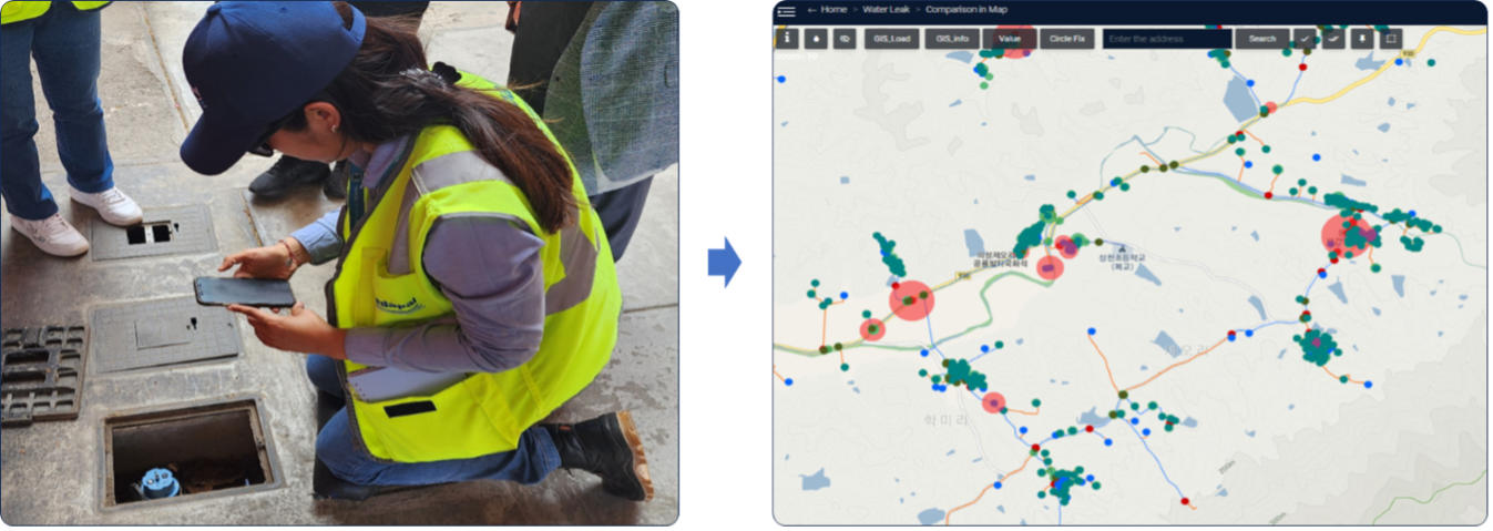
Figures 2 & 3: M2 pressure sensor deployment


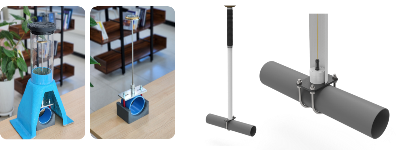
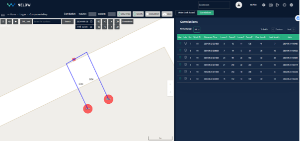
Figures 3 & 4: M2 pressure sensor deployment

Figure 5: M2 pressure sensor deployment
Using Simulations to Support AI in Water Management
Detecting water leaks isn’t just about placing sensors. Advanced tools like the EPANET Toolkit for Python are helping utilities simulate different leak scenarios. These simulations account for uncertainties, such as varying water demand, ensuring the system is ready for all kinds of situations.
Step-by-Step: Using AI to Identify Leak Locations
1. Pressure Boundaries: Simulations help set pressure limits at each sensor. These limits define the normal range of pressure the system should have.
2. Real-Time Alerts: If the pressure at any sensor drops below the normal range, the system triggers an alert, indicating a possible leak.

Figure 6: System general leakage alert
3. Leak Identification: By monitoring pressure changes over time, utilities can identify where leaks are happening and how severe they are.

Figure 7: Virtual leaks location
Key Benefits of AI-Powered Leak Management Systems
Once a leak is detected, finding its exact location and size is crucial. This is where AI comes in. By using pressure data collected from sensors, AI water management can predict the location and magnitude of leaks with impressive accuracy.
How AI Helps
- AI is trained using pressure drop data from simulations.

Figure 8: Pressure drops detected by M2 sensors for varying leak intensities at node ID 4
- When a leak occurs, the AI analyzes the pressure drop and predicts the leak’s location and size.
- The results are displayed on a network map, making it easy for operators to locate and fix the issue quickly.
For example, in a test scenario with three virtual leaks, the AI accurately pinpointed the location and severity of each leak, demonstrating its potential to transform leak management.

Figure 9: Random forest regressor AI model for predicting leak characteristics
Key Benefits of AI-Powered Leak Management Systems
- Faster Leak Detection: Detecting water leaks and AI provide real-time insights, allowing utilities to respond to leaks immediately.
- Precise Localization: Simulations and AI models help pinpoint leaks, reducing repair times and costs.
- Scalability: The system can adapt to networks of different sizes and complexities.
- Improved Efficiency: By shifting from reactive to proactive maintenance, utilities can extend the life of their infrastructure and improve service delivery.
Looking Ahead: The Future of AI in Water Management
As water utilities continue to adopt digital solutions, tools like pressure monitoring, simulations, and AI will play a central role in building smarter and more sustainable water networks. These technologies not only save water but also enhance operational efficiency, paving the way for a future of intelligent water management.

